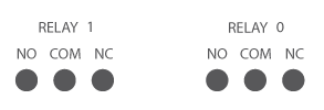
The relay outputs map to directly to the GPIO 40 pin header. The default connections are as follows:
Relay 0 => pin 38
Relay 1 => pin 37
These pins must be setup as outputs.
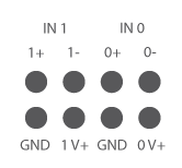
The opto-isolator inputs are mapped directly to the GPIO 40 pin header. The default connections are as follows:
Input 0 => pin 36
Input 1 => pin 33
These pins must be setup as inputs.
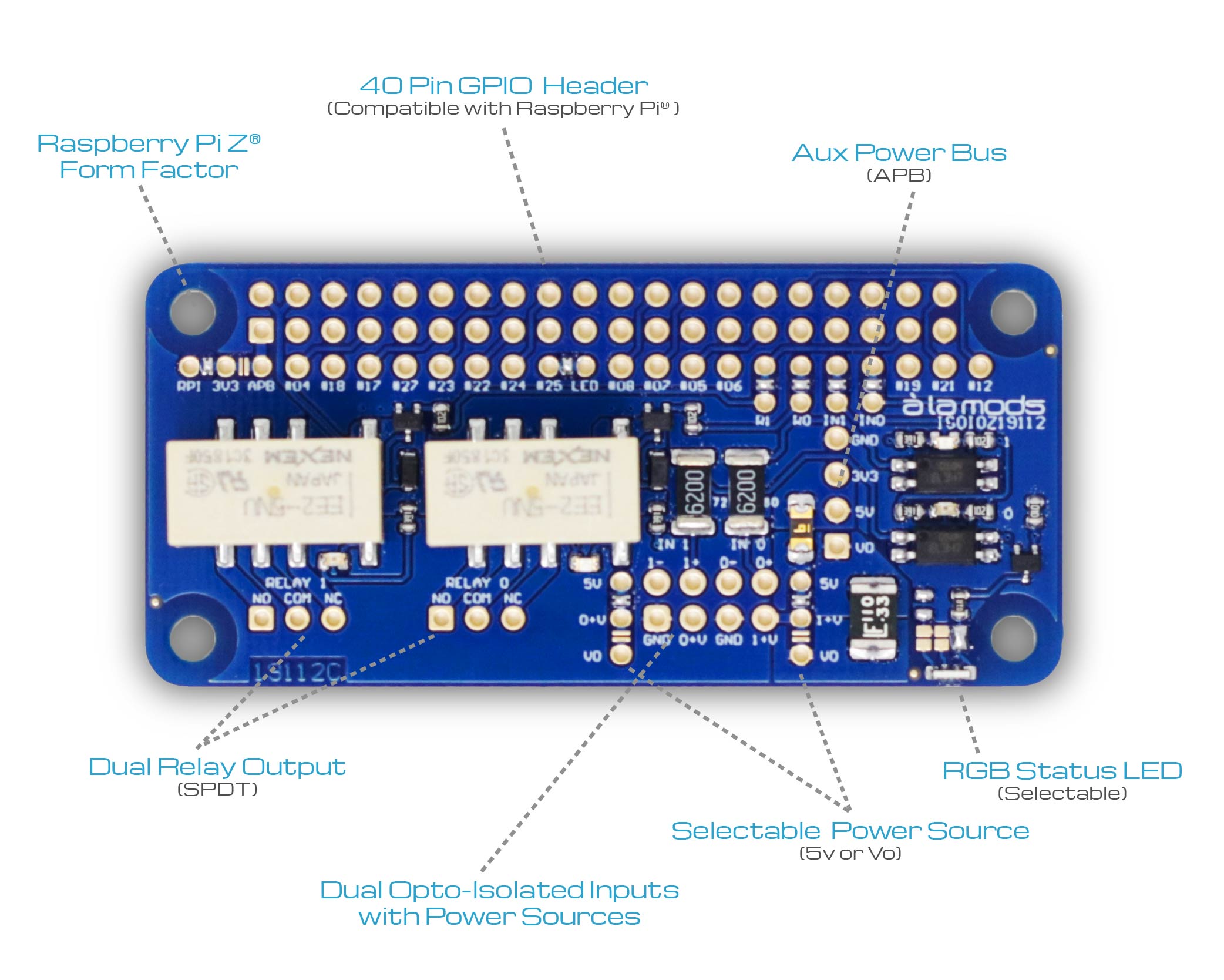
The à la mods APB is an additional stacking bus to distribute additional power up the stack of modules.
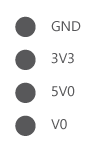
When the à la mods power supply module (PWR1Z19373 or PWRZ19128) is used, the APB bus contains additional power capability for the 5Vdc & 3.3Vdc plus an additional power source V0 that is directly connected to the input of the power module.
The ISOIOZ19112 module has several à la mods Dual Jumper selectable options to increase its flexibility.
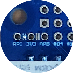
The module 3V3 power selection jumper determines where the 3V logic will receive its power from. In most cases the 3V3 power can be provided by the host controller (i.e. Raspberry Pi). This is the default shown in the image. Because the host controller may not have the power capability needed this jumper can be moved to the "APB" position which then connects the modules logic power to the Auxiliary Power Bus (this requires an à la mods power module in the stack).
WARNING!!! Do not connect 3V3 to both power sources at the same time!
The control I/O jumpers affect the GPIO header pins used for the module I/O control and monitoring functionality. By default they're connected to the GPIO pins identified above. By removing the solder bridge these control signals can be remapped to other GPIO pins.