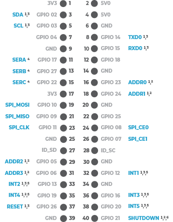
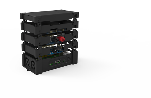
Although the à la mods "M" series Smart modules target many of the GPIO lines shown for communication and
control purposes, many of these are optional depending upon the specific module.
The minimum I/O requried by the Smart modules is generally the SPI I/O and ADDRx lines for communication.
It is the ADDRx lines that provide the individual communication of each module within a stack of
modules.
All non-SPI lines are configurable and can be disconnected or moved on the GPIO bus if needed.
NOTES:
- Jumpered GPIO lines.
- GPIO line should be jumpered for communications. Default is jumpered.
- Module Dependent. Default on most modules is NOT jumpered.
- Used for serial bus modules (i.e. SERM17428, etc.)
- INTx are optional.
- Shutdown is only used on power modules.
The à la mods "Z" series modules use the GPIO bus differently. These modules
DO NOT employ the ADDRx and INTx lines. While some of them
do utilize the SPI bus for communication, they are only multiplexed by the CE0 and CE1 lines of the
SPI bus, and therefore not intended for the extensive stacking capability like the "M" series modules.
SMART MODULE COMMUNICATION
Most all à la mods smart modules ("M" and "Z" series) communicate to the host processor via the
SPI bus and an internal module register set. The SPI bus is the transport mechanism for the control
and data information while the internal module registers provide the interface to the control and
status processes. This is much the same as many sensor ICs on the market that utilize internal
registers and either the SPI or I2C bus.
The SPI communication transport protocol is the same for all modules, but the internal registers are
specific to each module's functionality. For internal register details reference the specific module
user guide.
The physical à la mods SPI communication link consists of eight GPIO lines including:
- Four SPI lines (SPI_MOSI, SPI_MISO, SPI_CLK and SPI_CE0 or SPI_CE1)
- Four address lines ADDR0 - ADDR3 ("Z" series do NOT use these lines. CE0 or CE1 only)
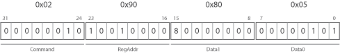
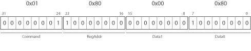
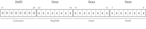
The SPI communication transport consists of a set of command messages that transfer information
between the à la mods smart module and the host processor. These commands consist of four byte
messages structured as illustrated in the figure below.
All messages are transmitted MSB first.
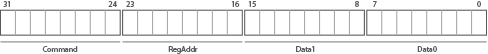
The command byte instructs the module what to do with the last two data fields of the four byte
message or can instruct the module to perform other actions. For the list of supported module
commands see the specific module user guide.
The general register commands include:
- Internal register read: 0x00
- Internal register address pointer setup: 0x01
- Internal register write: 0x02
Register Address Byte (RegAddr)
The Register Address byte instructs the module what internal register will be accessed in the
current command message for a write instruction or the next command message in the case of a
register address pointer setup message for a read operation.
The register address range is the full byte: 0 - 255
Data Bytes (Data1 & Data0)
The data bytes contain the actual data that will be transferred into the internal register in the
case of a write command or transferred to the host processor in the case of a read command.
The register write operation is a single command message that contains the write command (0x02), the
internal reigster address and the two byte data that is to be written.
The register read operation first consists of a internal address register pointer setup message (command
= 0x01) followed by an internal register read message (command = 0x00)
The register read operation actually occurs every command message. Since the SPI bus is a bi-directional
synchronous bus, data is transferred back to the host processor every time a message is sent. Therefore,
unless the internal address register pointer is changed the data bytes from the same internal
register will be returned from each command message. That includes any read or write command message.
This is useful for polling operations where write commands can occur to adjust a control register
while continually reading a status register.
BASE REGISTERS
Every à la mods smart module contains a base set of registers providing a common set of
information about the module and control of the on board RGB LED. These include:
0x80 - Decimal Model Number (read-only)
This register contains the 16 bit value of the decimal part of the model number. For example,
the ADIOM18063 decimal model number is 18063. Data1 field is the high byte of this number and
Data0 is the low byte.
0x81 - Revision (read-only)
This register contains the hardware and firmware revision numbers.
0x82 - Firmware Type (read-only)
This register contains an ASCII code that represents the type of firmware executing in the
modules processor. This includes:
0x90 - RGB LED Control (read-write)
This register controls the state of the on-board RGB LED.